Raspberry Pi: Connecting Hardware
Wednesday 19th July 2017 12:35am
The Raspberry Pi comes with upto 40 pins that allow a vast number of electronic devices to be connected: LED’s, switches, motion detectors, temperature sensors, Global Positioning Systems (GPS) etc.

GPIO Pins
These pins are referred to as General Purpose Input Output (GPIO) pins and are used to control or communicate with these devices:
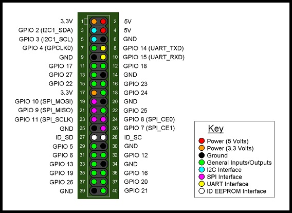
Using the GPIO Pins diagram you can see some of these pins offer a source of power as either 3 volts (pins 1 and 17) or 5 volts (pins 2 and 4).
To complete any circuit we need to also connect to any one of the ground pins (6, 9, 14, 20, 25, 30, 34 and 39).
The remaining pins (with the exception of pins 27 and 28) can be programmed to operate as either an input or an output.
The Python GPIO library that comes with Raspbian makes it easy to enable the individual GPIO pins. When using the Python GPIO library we need to always run with administrator privileges so we start with the command sudo (short for super-user do).
Open a terminal window and type the following to start the Python interpreter:
sudo python
This will display the version of python you currently have installed:
Python 2.7.9 (default, Mar 6 2015, 00:52:26)
[GCC 4.9.2] on linux2
Type "help", "copyright", "credits" or "license" for more information.
>>>
To start working with the library type:
import RPi.GPIO as GPIO
When referencing the pin numbers there are two methods we can use, either the numbering of the pins on the PCB (Printed Circuit Board) or the Broadcom naming system. These are referred to as BOARD or BCM; for example in the diagram above pin 12 (BOARD) is also called GPIO 18 (BCM). In these tutorials I will use the BOARD numbering system.
GPIO.setmode(GPIO.BOARD)
Next we need to define the pin number and whether the pin will be used as an input or as an output. If we were to connect an LED to light up when something happens this would be classed as an output. Connecting a switch to do something when pressed this would be an input.
LED_PIN = 12
SWTCH_PIN = 14
GPIO.setup(LED_PIN, GPIO.OUT)
GPIO.setup(SWTCH_PIN, GPIO.IN, GPIO.PUD_DOWN)
Outputs
To light up an LED by sending 3 volts to the pin we set the output to HIGH:
GPIO.output(LED_PIN, GPIO.HIGH)
To turn off the LED by setting the pin to zero volts i.e. set the output to LOW:
GPIO.output(LED_PIN, GPIO.LOW)
Inputs
If we want to be notified when a switch is pressed by responding to 3 volts being sent to a pin we need to continually check that pin for voltage changes using a while True loop.
previous_state = False
current_state = True

while True:
  previous_state = current_state
  current_state = GPIO.input(SWTCH_PIN)
  if current_state != previous_state:
    new_state = 'HIGH' if current_state else 'LOW'
    print('GPIO pin %s is %s' % (SWTCH_PIN, new_state))
Press and hold down the switch and the pin will go HIGH. Release the switch and the pin will go back to LOW:
GPIO pin 14 is HIGH
GPIO pin 14 is LOW
GPIO pin 14 is HIGH
Press CTRL+C when you want to exit.
NOTE: Requesting a GPIO pin be set to HIGH when it is already HIGH would result in a warning being displayed. To disable this feature set the warnings to False:
GPIO.setwarnings(False)
Once you have finished you can issue a command to cleanup any pin connections:
GPIO.cleanup()
